Welcome to the latest edition of Coasters-101, the series where we talk about how roller coasters are designed and built. Let’s talk about modeling a roller coaster track on the computer. There are many different 2D and 3D CAD packages you can use. This example utilizes a 3D CAD software called CATIA (which stands for computer aided three dimensional interactive application). How do you model a roller coaster track? There are many different methods depends on which program you are using. You can see my previous attempts at making track with the cantilevered coaster model.
Matt Schmotzer of Print My Ride Detroit has some excellent video tutorials on his YouTube channel showing how you can design a roller coaster in the NoLimits 2 software, export the data to Excel, then import it into a 3D CAD system such as SolidWorks:
The first question you always having to ask when modeling something on the computer is what is your design intent? What is the purpose of the model and what are your goals. Are you trying to design a real roller coaster? Or making a model for 3D printing?
Here are the requirements I laid out for constructing a coaster’s track CAD model for this particular example:
- Smoothness – the track must not have any crazy twists or rough transitions
- Flexibility – the track must be easy to modify
- Lightweight- the file size must not be too big otherwise it will bog down my pc
There are multiple ways you could design a roller coaster in CAD. Here is one method you could try.
Three 2D Sketch Method for Designing a Roller Coaster
The following is a tutorial of the steps used to creating 3D roller coaster track in CATIA using basically only three 2D sketches: one for the top layout view, the profile view (if the track were made in one long, straight line), and the banking.
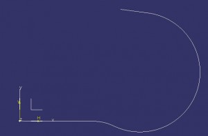
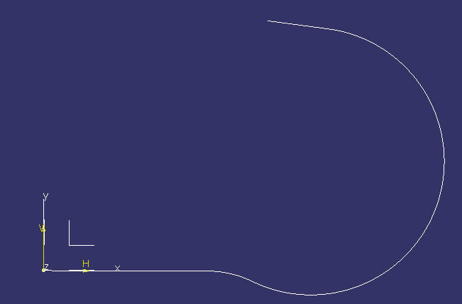
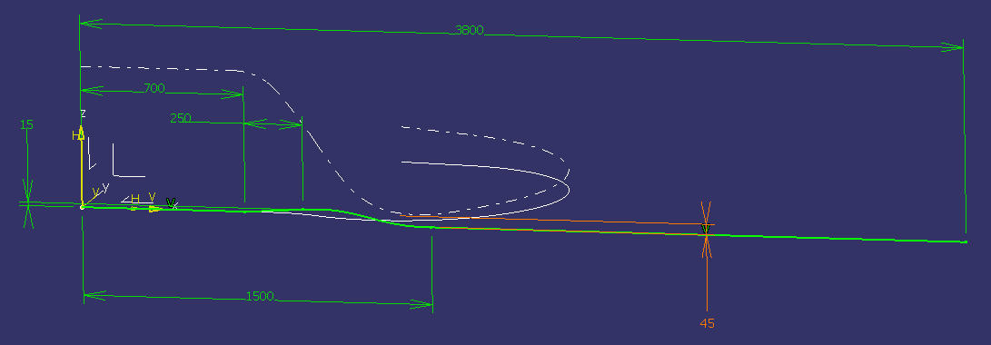
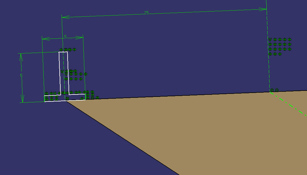
- Start with a sketch showing a plan or overhead view of the track layout. Measure the sketch length so you know how long it is. If you’re recreating a real roller coaster this is a good check.
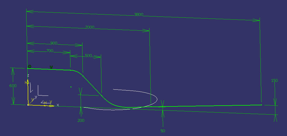
- For the height of the track, make a second sketch that is more like a graph showing the track height as it moves along the entire length of the track. My example track starts with a height of 600, dips down to 50, and then slowly goes up to 150. I’m ignoring units for now.

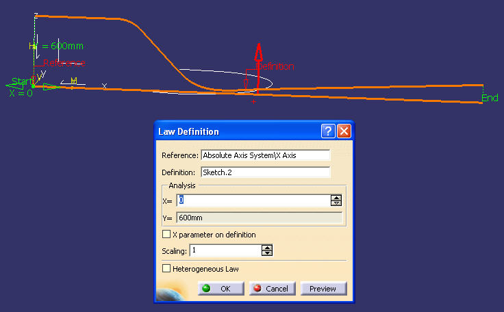
- Next, create a Law based on the second sketch. A law in CATIA is a function that can vary the value of a parameter.
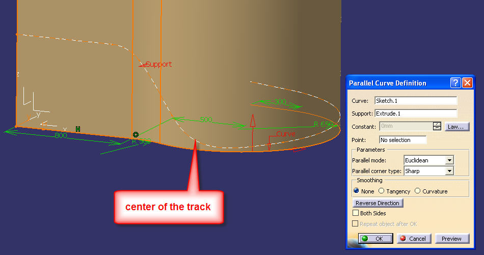
- To get the centerline of my track; first make an extruded surface from the first sketch in the Z direction, taller than the highest point of the track. Then make a parallel curve based on the first sketch, and with an offset based on the Law from step #3. (You may have to go back and adjust the second sketch to get the dips and hills exactly where you want them to be).
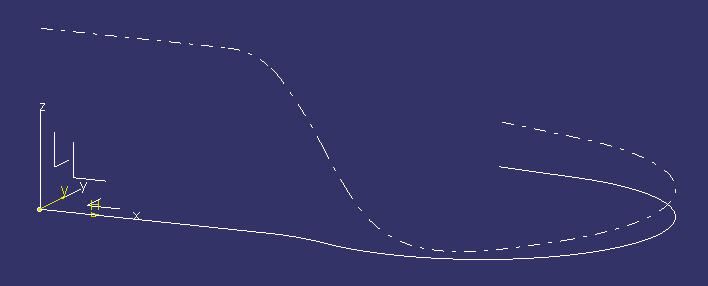
- Hide the extruded surface and the second sketch, so it’s easier to see the course centerline.
- Now make a third sketch graphing how the track will bank along the entire length. I started the graph at 0 (degrees), then went to +15, and then to -45, which I kept for most of the turn in the track. Then make a second Law with this sketch.
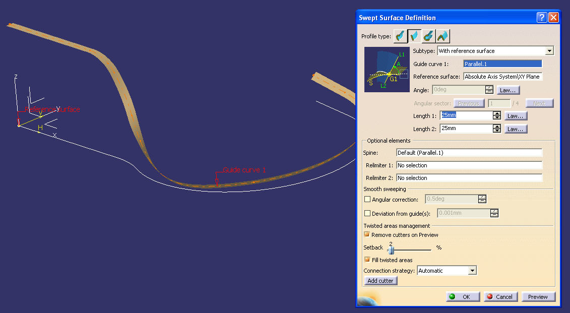
- Now you can add the swept surface, using the Law to define the banking angle. One of the nice things about this method is the ability to go back to the Law sketches and adjust heights and angles to get the track the way you want it.
- From here we have a center line of our track and the swept surface that has the banks in the track. Since the two rails are the identical shape and are the same distance apart, I will add them as a single Rib. But each rail could be modeled as its own Rib. (The cantilevered coaster model was created using only ribs, no laws were used.)
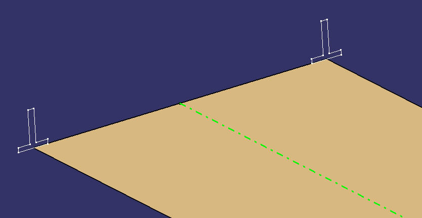
- Make a sketch at one end of this section of track, and draw the rail profile. Add a vertical center line (construction mode) and mirror the rail profile to the other side. (I made T-shaped rails, but you can make whatever shape you want; square, round, etc.)
- In CATIA, switch from the GSD workbench to the PartDesign workbench, and make the PartBody the active work object.
- Add the Rib to make both rails in the track. The profile is the sketch with both rail profiles. The center curve is the centerline. Change the Profile Control to REFERENCE SURFACE, and select the swept surface (this will make the rails bank based on the Law we used for that surface).
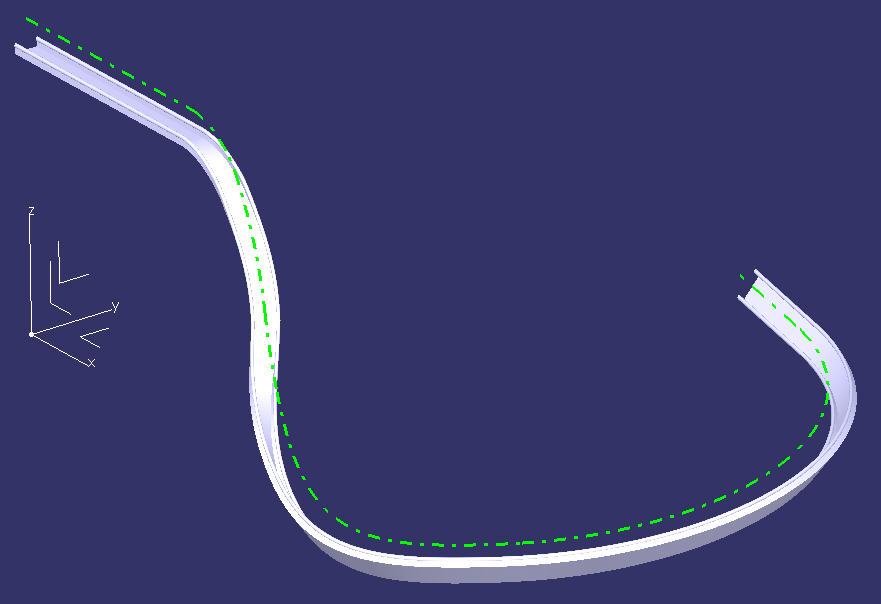
- Hide the Sketch, swept surface, centerline and other construction stuff to just see the track.
- Now the hard part – add the support structure like you’ve seen done with my cantilevered roller coaster model.
- Note that it’s important that the track centerline have no sharp transitions and nice, smooth corners. For fun, use the Fly command to “take a ride” down the track. Add some poles or trees or buildings to make the flying look more realistic.

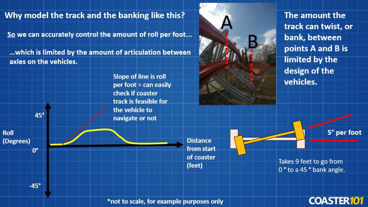
Now you may be sitting there wondering why you would build a 3D roller coaster in CAD using this method of 2D sketches. One possible reason for designing the banking of a roller coaster in a 2D sketch is so you can easily check the degree of roll per foot. When designing the layout, the track can only twist (or roll or bank) a certain amount over a distance defined by the limitations of the vehicles.
On Holiday World’s YouTube channel there is a great video of the late Will Koch explaining how when they moved cars from the Raven to run on the Voyage they had to modify them because Voyage’s roll rate was greater than that of the Raven. When the track banking rate is shown in a 2D chart you can easily check to make sure that the roll rate is feasible for the vehicle. The slope of the line is the degree (amount of twist) per foot (distance).
Now we’ve created a track. Not too hard. But there is something else to consider. In the above design we have the track rotated around the center of the two rails. You may have read in our previous Coasters-101 article that in these types of arrangements, the center of gravity of the passenger is accelerated toward the center of the curve. This results in the passenger being thrown against the side of the car or against another passenger. The ride must not put too much strain on a rider.
To correct for this acceleration, the track should be rotated around the center line, or heartline of the passengers (roughly just above the center of a human torso). Thus, the acceleration of the passengers to the inside of the curve is greatly reduced. I believe most modern roller coasters are designed this way, with the banking rotated around the heart of the riders, a point which will be some distance x above the center of the rails. So, how do you rotate the rails about this heart-line using this track construction method?
If you just consider the “centerline” to be the “heart-line”, and modify the sketch of the rails so the rails are the appropriate distance below the heart-line, this will provide the track you want. Although the higher pivot point will cause the track to really swing, as the figure shows. And now you can go model your very own virtual 3D roller coaster! Have fun and feel free to share your designs with us here or on our Facebook page.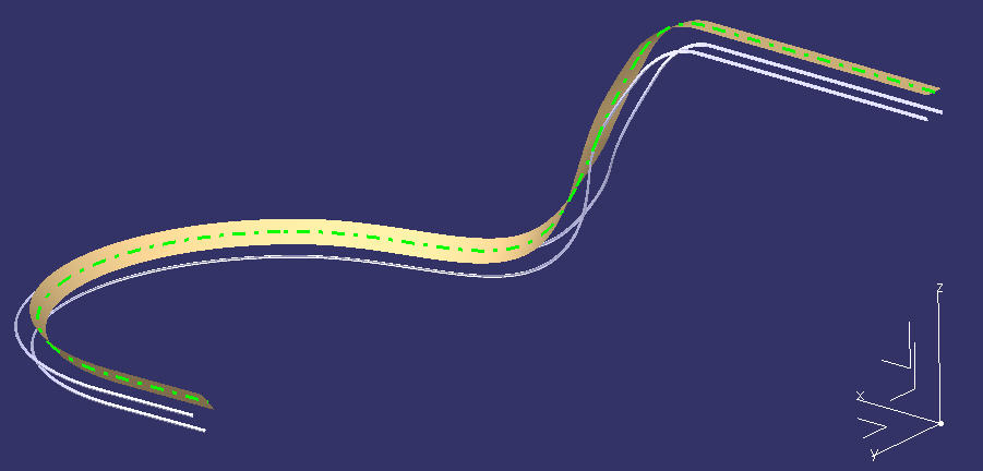
Update March 2022
Here’s a quick demonstration video showing how to use the three 2D sketch method to model roller coaster track in a 3D CAD system:
To learn more about how coasters are designed check out Coasters 101: An Engineer’s Guide to Roller Coaster Design.
Have you ever tried to model a roller coaster in a CAD system before? Which CAD software did you use and which modeling method? Let us know in the comments below!


Sounds like a waste of time. You should just use nolimits 🙂
You can’t do stress analysis in No Limits 🙂 (although maybe that is a feature they will add in No Limits 2, if it ever comes out.)