If you are a frequent visitor to Coaster101, you may have seen some of my CATIA amusement park ride computer models, like this. You may also have been asking yourself or wondering how I created those computer models. Well today I am going to explain in a little bit further detail on the process I have used to recreate those attractions on the computer.
I use a program called CATIA Computer Aided Three-dimensional Interactive Application), which is the most powerful and widely used CAD (computer aided design) software of its kind in the world.
If you’ve ever used No Limits simulator there is an excellent Wicked Twister recreation so I am going to use that to help me out. Keep in mind that this is just one approach of literally thousands of different ways of doing it. If you have a other suggestions I would love to hear them!
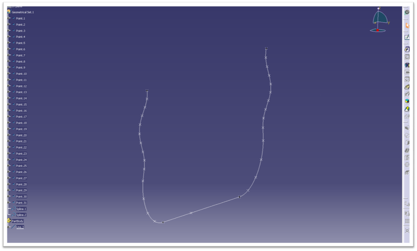
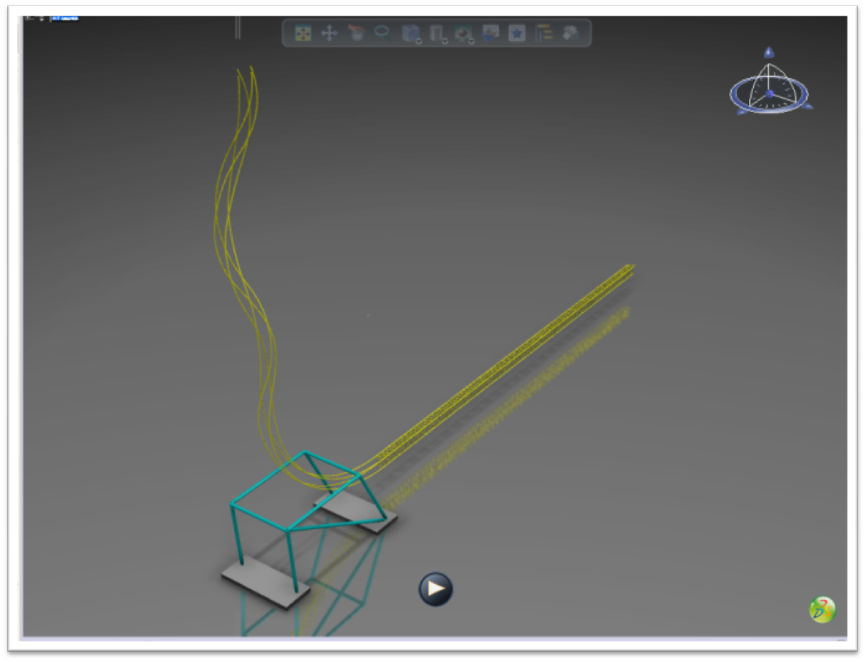
The first thing I did was get the coordinates from all of the node points in the No Limits model. I created all of these points in a CATIA part. Be careful of the axis system, CATIA’s default axis is not necessarily the same as No Limits in terms of which direction is X, Y, or Z is. Next, connect all of the points with the spline command. This is the result thus far. You can see the basic profile layout, also called the center or heartline of the coaster.
Now we need to make the shape of the track. This are the dimensions I used for the track.
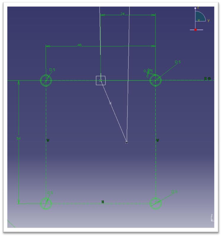
I have never seen an actual spec from Intamin so I had to do a little investigating and guess work. This is what’ve I’ve come up with. From an old Millennium Force flyer I learned the rails are 5 inches in diameter and only 3/8 inch thick (even at the highest g-force areas). Someone gave me an educated guess that the rails are 48 and 54 inches apart at the centerlines so I went with it. The rectangular tubes that hold the rails together I assumed to be 3 inch square tubing.
The important thing to notice now is that the rails are zero degrees with respect to the horizontal axis. This becomes critical when we get to the two towers and this angle will gradually increase, which makes the twisting helix.
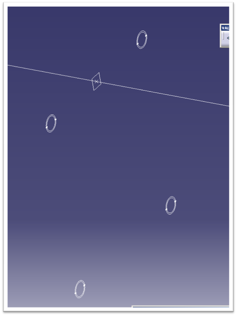
The basis of everything is right here. The centerline and the sketch for the rails.
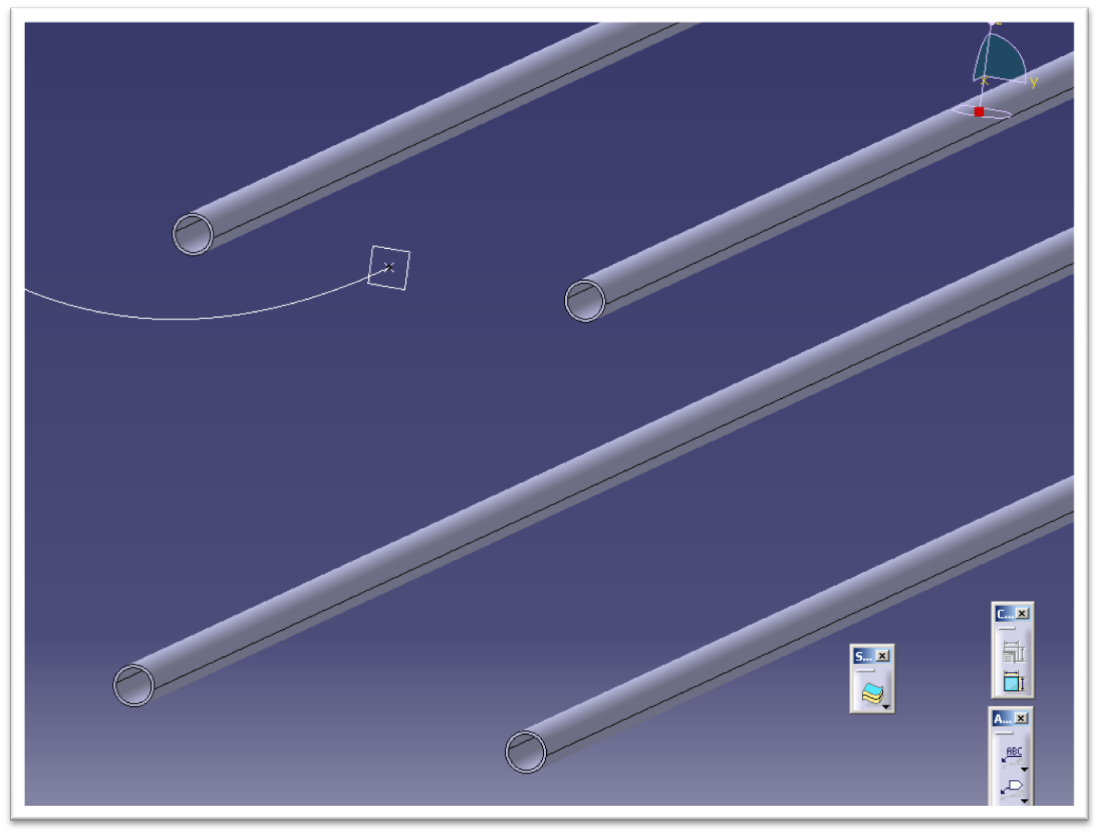
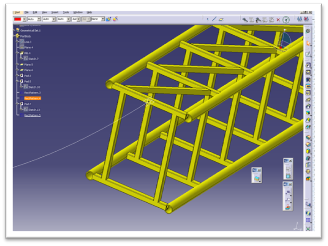
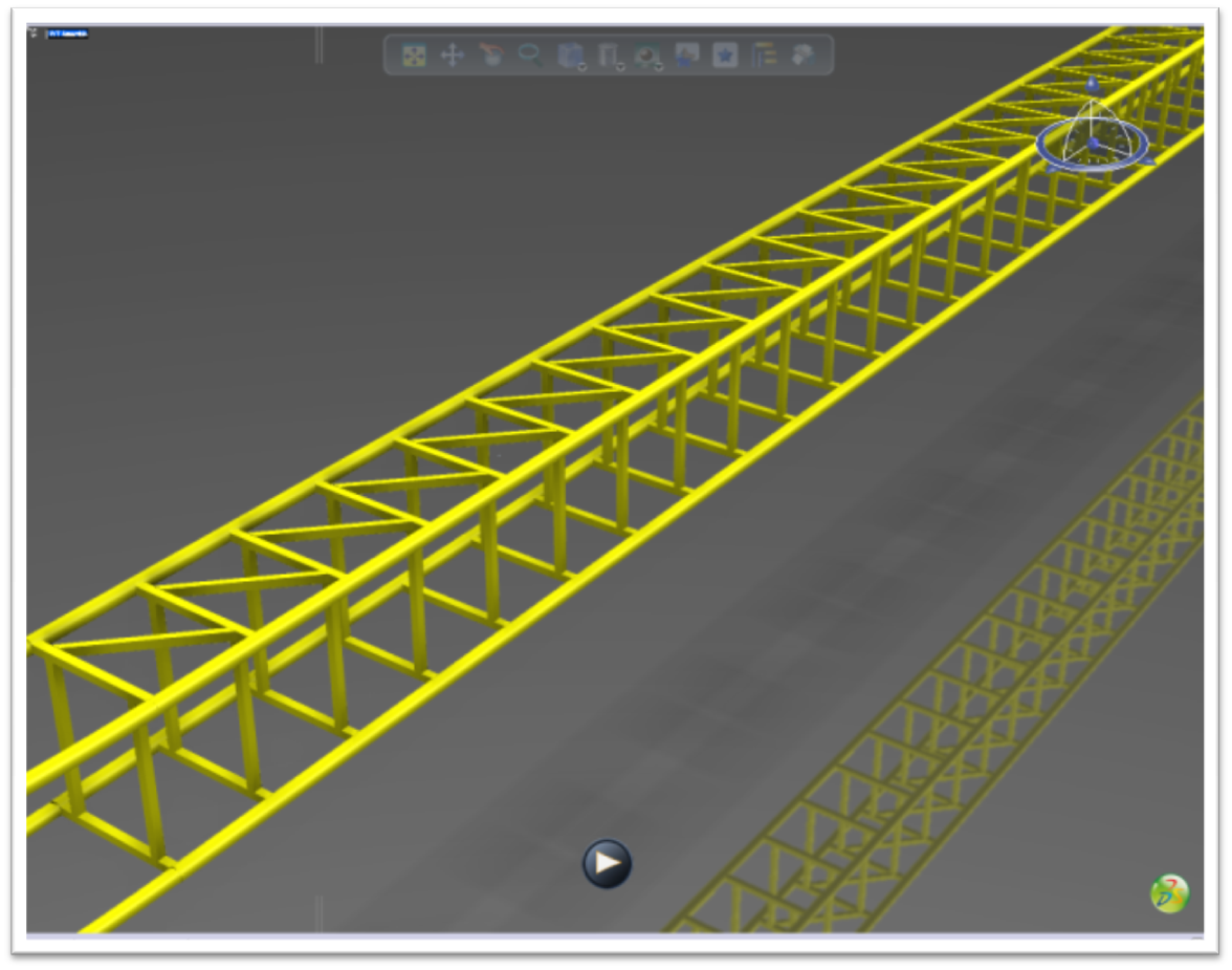
After I created the sketch for the rails, I used the rib command to extrude their shape throughout the length of the station and launch track segments.
After the rails were created I had to construct the connecting tubes, pictured here.
<

Next I began adding the diagonal cross bars. I only have to sketch one of them on the straightaway then I can simply pattern the rest.
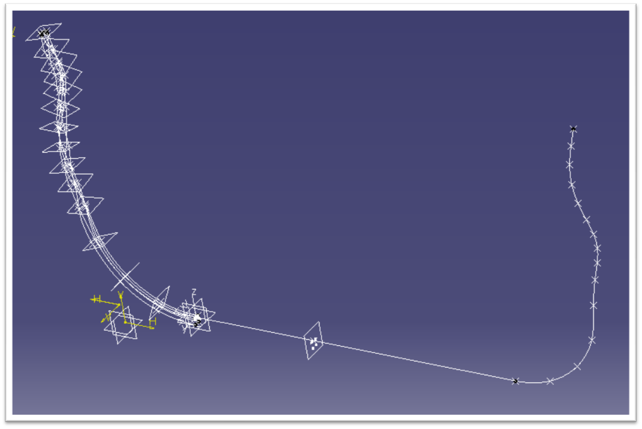
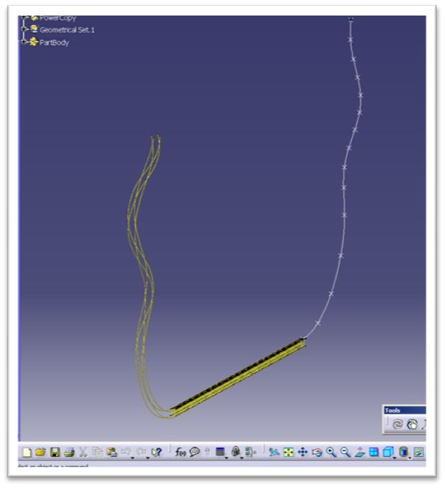
The hard part now is the spikes on the end. Remember the critical angle I mentioned earlier? At every node point starting from the fourth one out of the station the track now rotates 45 degrees about the center. I created points where the rails will go and then connected them with a spline, giving the shape you see here. I can then sketch a circle on the end and rib it through the spline, just like I did earlier, thus creating the rails.
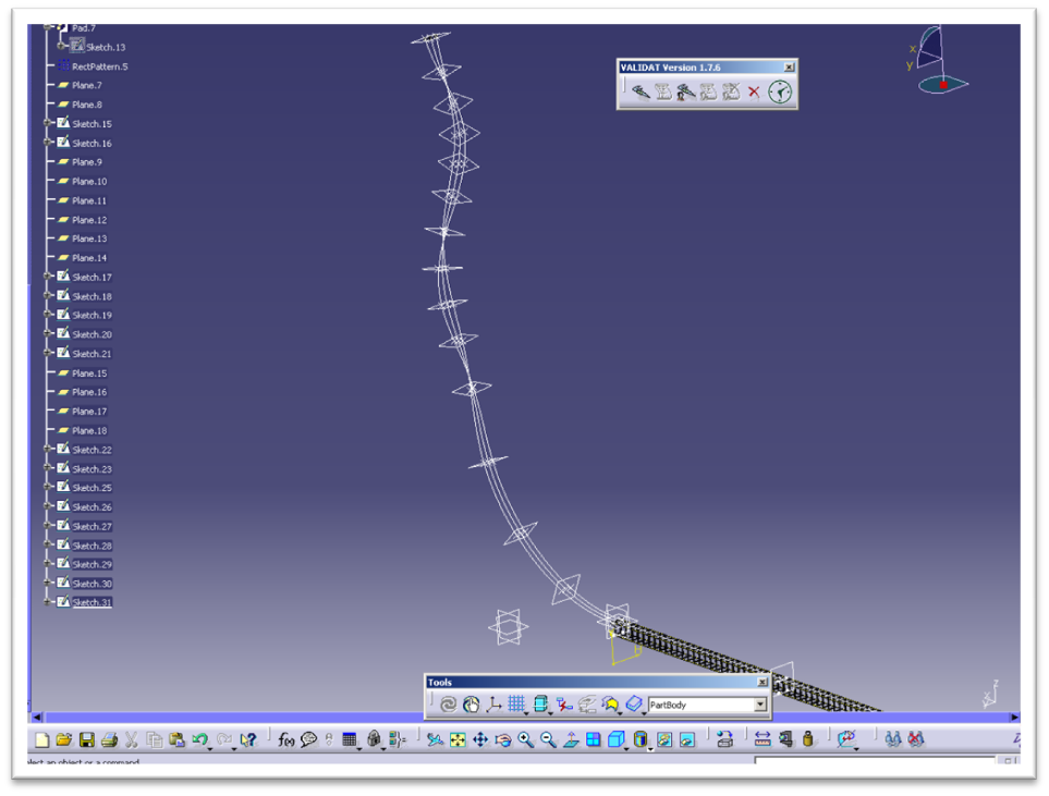
This is what all of the construction geometry looks like, and by construction geometry I mean all of the points, planes, lines, splines, axis and sketches. These elements are used to construct the solid.
Next, I ribbed the twisting splines. After all of that, here is the result of our progress, which is as far as I am going to go today. The only other thing I will do now is to quickly construct some simple concrete footers and steel supports for reference.
I saved my assembly as a 3d xml file and exported it to 3D Via and here it is for your enjoyment.
Would you be interesting in learning more and reading additional features like this one? Let us know in the comments or in the forum!
Thanks for reading.


Thank you so much!
I’m a university student in South Korea. and your article is so helpful. I’m going to make or get a 3D rollercoaster model for Finite Element Analysis with ANSYS.
At this time, I have no 3D model, so I think I have to make it.
If you spare any 3D rollercoaster model for me, I would be very grateful to you.
Have a nice day~
from. KS in Korea.